The goal for this lab is to learn how to align optical components on an optical breadboard to make an optical system. Typically, optical engineers or laser physicists are only given an optical diagram and are expected to be able to know how to build the optical system from that diagram. This is just like a contractor only getting a blueprint for a house, or an electrical engineer only getting a circuit diagram. Here we will give you several diagrams for various optical systems and have you build those systems. We will start off easy with a simple optical diagram and almost all of the directions to build the optical system. Then, in the last part we will make things more challenging with increasingly more complex optical systems and less directions for how to build the system.
Part 1: Align a Laser

Goal: Align a laser through two irises.
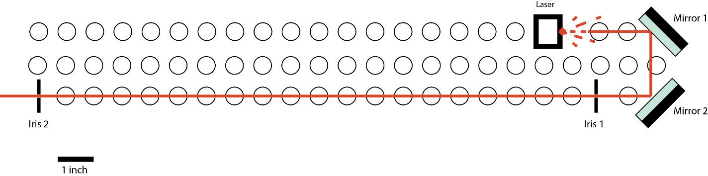
Optical Diagram: Here is your first optical diagram. Let’s see if you can build it! In this diagram, we show you the screw holes on the optical breadboard as a series of circles. You can see the placement of the laser, mirrors, and irises. Essentially, we are going to align the laser beam to the straight line set by the two irises along the screw holes. To do that, you will use two mirrors, mirror 1 and mirror 2, and two irises, iris 1 and iris 2.
Optical Diagram: Here is your first optical diagram. Let’s see if you can build it! In this diagram, we show you the screw holes on the optical breadboard as a series of circles. You can see the placement of the laser, mirrors, and irises. Essentially, we are going to align the laser beam to the straight line set by the two irises along the screw holes. To do that, you will use two mirrors, mirror 1 and mirror 2, and two irises, iris 1 and iris 2.
Key design points:
1) Bolt down a laser close to the end of one side of the breadboard, leaving room for the first mirror at the end of the same row.
2) Get two irises out and set both irises so that their holes are a height of 4.5 inches off the optical table.
3) Screw down one of the irises where mirror 2 will be. Or for even better alignment, you can screw down the iris in the same column of screws as where mirror 1 and mirror 2 will be, but at the end of the optical breadboard. (Hopefully, by now you are getting the feel for consulting the Optics – Rules to Live By! guide for how to screw things down, or put things together. You’ll need to do this again to make sure that you screw down the iris appropriately in the correct position. We’ll assume from now on that you will know to consult this guide and will continue on without these notes.)
4) Now we can coarsely align mirror 1. Do this by placing the mirror on the optical breadboard without screwing the mirror down. Make sure the beam hits the center of the mirror. Then, translate the mirror back and forth along the screw holes just a little bit, getting closer or further away from the laser. (You are moving perpendicular to the iris.) This movement back and forth is one degree of freedom that you have to place the mirror. Notice that by moving the mirror back and forth you change the position of the beam. Now rotate the mirror by loosening the post holder screw and rotating the post attached to the mirror. This is the second degree of freedom that you have to place the mirror. Notice how this movement changes the angle of the beam. Use these two degrees of freedom to center the beam on the iris. Tie the mirror to the optical breadboard using the base clamps.
5) Now screw down both irises in the row next to the laser, as indicated in the optical diagram. One will be close to one end of the breadboard, but will leave room for mirror 2. The other will be on the other side of the breadboard. (Remember: further apart makes the alignment better).
6) Coarsely align mirror 2 so that the beam hits the mirror dead on and so that the beam is roughly aligned to the two irises.
7) Now do a fine alignment of the beam to the two irises. To do the fine alignment you are going to use the two knobs on each mirror holder. You’ll notice that one knob moves the beam in x (horizontally) and one knob moves the beam in y (vertically). Close iris 1 and adjust the knobs on mirror 1 until the beam is aligned to the hole of iris 1. Then, open iris 1 and close iris 2, and adjust the knobs on mirror 2 so that the beam is aligned to the hole on iris 2. Repeat this procedure until the beam is aligned to both irises. You’ll notice that the beam will slowly move or “walk” into the right position. Thus, this procedure is called “walking the beam”. Essentially, what you are doing is setting the position of the beam with the first mirror and the angle of the beam with the second mirror. Now misalign your beam and use that principle to help you walk the beam to the right spot again. Hopefully, it took you a lot less time the second time around. Remember: mirror 1 controls alignment at iris 1, and mirror 2 controls alignment at iris 2.
- We want the laser as close to mirror 1 as possible, to limit the amount the beam will have diverged before it hits mirror 1.
- We want mirror 1 and 2 as close to each other as possible so that we will have the maximum range of motion for adjusting the beam.
- We want the irises as far apart from each other as possible, to make the alignment easier and more precise.
1) Bolt down a laser close to the end of one side of the breadboard, leaving room for the first mirror at the end of the same row.
2) Get two irises out and set both irises so that their holes are a height of 4.5 inches off the optical table.
3) Screw down one of the irises where mirror 2 will be. Or for even better alignment, you can screw down the iris in the same column of screws as where mirror 1 and mirror 2 will be, but at the end of the optical breadboard. (Hopefully, by now you are getting the feel for consulting the Optics – Rules to Live By! guide for how to screw things down, or put things together. You’ll need to do this again to make sure that you screw down the iris appropriately in the correct position. We’ll assume from now on that you will know to consult this guide and will continue on without these notes.)
4) Now we can coarsely align mirror 1. Do this by placing the mirror on the optical breadboard without screwing the mirror down. Make sure the beam hits the center of the mirror. Then, translate the mirror back and forth along the screw holes just a little bit, getting closer or further away from the laser. (You are moving perpendicular to the iris.) This movement back and forth is one degree of freedom that you have to place the mirror. Notice that by moving the mirror back and forth you change the position of the beam. Now rotate the mirror by loosening the post holder screw and rotating the post attached to the mirror. This is the second degree of freedom that you have to place the mirror. Notice how this movement changes the angle of the beam. Use these two degrees of freedom to center the beam on the iris. Tie the mirror to the optical breadboard using the base clamps.
5) Now screw down both irises in the row next to the laser, as indicated in the optical diagram. One will be close to one end of the breadboard, but will leave room for mirror 2. The other will be on the other side of the breadboard. (Remember: further apart makes the alignment better).
6) Coarsely align mirror 2 so that the beam hits the mirror dead on and so that the beam is roughly aligned to the two irises.
7) Now do a fine alignment of the beam to the two irises. To do the fine alignment you are going to use the two knobs on each mirror holder. You’ll notice that one knob moves the beam in x (horizontally) and one knob moves the beam in y (vertically). Close iris 1 and adjust the knobs on mirror 1 until the beam is aligned to the hole of iris 1. Then, open iris 1 and close iris 2, and adjust the knobs on mirror 2 so that the beam is aligned to the hole on iris 2. Repeat this procedure until the beam is aligned to both irises. You’ll notice that the beam will slowly move or “walk” into the right position. Thus, this procedure is called “walking the beam”. Essentially, what you are doing is setting the position of the beam with the first mirror and the angle of the beam with the second mirror. Now misalign your beam and use that principle to help you walk the beam to the right spot again. Hopefully, it took you a lot less time the second time around. Remember: mirror 1 controls alignment at iris 1, and mirror 2 controls alignment at iris 2.
Part 2:

Part 3: Install a Telescope

Goal: Increase the beam width and collimate the beam using a telescope.
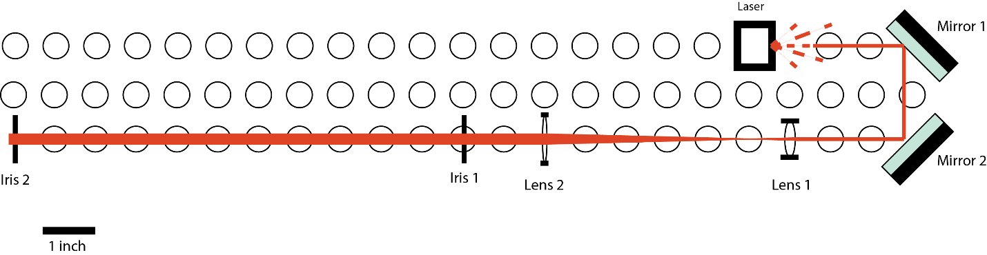
Design: By using two plano-convex lenses, lens 1 and then lens 2, we can build a telescope. Lens 1 has a focal length of f1 and lens 2 has a focal length of f2. Placing the lenses f1 + f2 apart allows you to expand or shrink the beam by a factor of f2/f1. Moving one of the lenses so that the distance between the lenses is not quite f1 + f2 can correct for a diverging or converging incident beam.
Optical Diagram: To expand the beam, the lens with the smaller focal length should be lens 1, and the lens with the longer focal length should by lens 2. The distance between lens 1 and lens 2 should be equal to f1 + f2. Here lens 1 has a focal length of 1” and lens 2 has a focal length of 5”. The distance between them is 6”.
Procedure:
1) Move iris 1 to make room for your lenses.
2) Make sure your setup is still aligned through the irises with no lenses.
3) Select two lenses that you would like to use to expand the beam and mount them in optical mounts.
4) Insert lens 1 close to mirror 2, but don't bolt it down firmly yet. Let’s first coarsely align the lens. To do this, roughly set the height of the post (y) so that the beam hits the center of the lens. Next, make sure that the lens/lens mount is perpendicular to the beam axis by eye.
5) Now let’s do the fine alignment. First, screw the lens mount to the optical breadboard and adjust the slop of the lens mount to fix any x alignment. The beam should be centered on the lens in x and the beam exiting the lens should be aligned to both irises in x. Next, move the post height (y) more precisely so that the exiting beam is aligned to both irises in y. Tighten the post collar to make sure this height doesn’t change. The beam should be centered on the lens in y and the beam exiting the lens should be aligned to both irises in y. Finally, rotate the post attached to the lens until the back reflection of the lens is perfectly on top of the original beam. Tightly bolt down the lens.
6) If everything looks good, insert lens 2 using the same procedure as lens 1, except with one variation. In the coarse alignment, you’ll need to make sure to roughly adjust the z position of the lens. This should be at a distance of f1 + f2. In the fine alignment, you are going to finely align the z position of the lens. This will set the collimation of the beam. To do this, image the beam very far away (at essentially “infinity”) and focus it at that location. Focusing the beam at “infinity” will create a collimated beam. To finely adjust the z position, you can bolt bases to the optical table to create a track in z. Moving the mount back and forth along this track will allow for fine z movements. Translation stages in x, y, or z can be also be used to have control over the fine alignment of the lens.
Part 4: Align an Optical System
Goal: Build an optical system from an optical diagram. You will build two systems with increasing complexity. Test your skills!
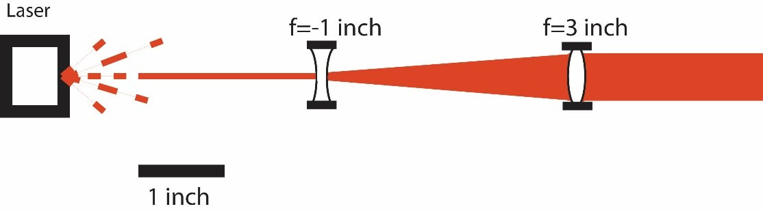
System 1: You can choose either a) the spatial filter or b) the beam expander with the diverging lens.
System 1: You can choose either a) the spatial filter or b) the beam expander with the diverging lens.
b.)

System 2: You can choose either a) the spectrometer or b) the microscope.
a.)
a.)
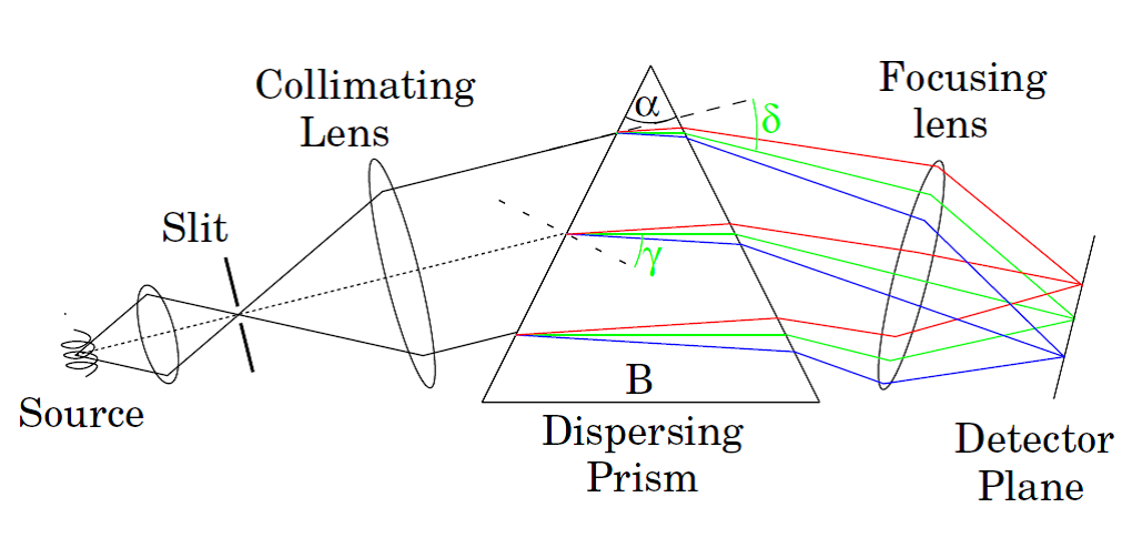
(Image Credit: Mcleod Lab – from ECEN Advanced Optics)

